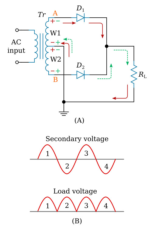
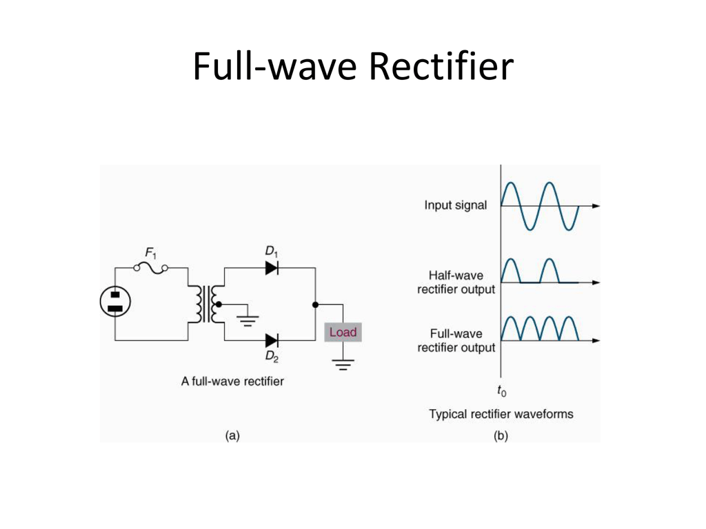
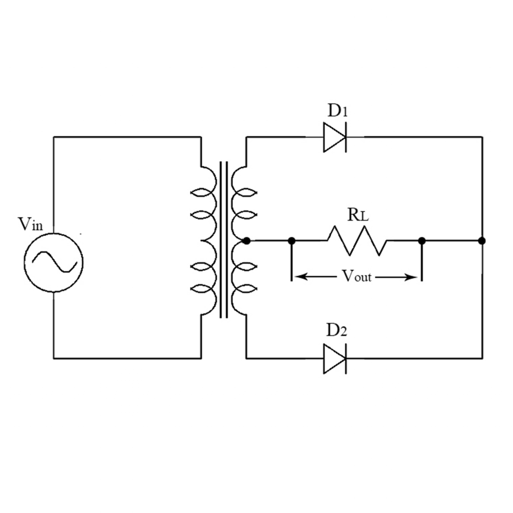
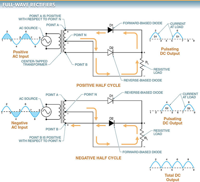
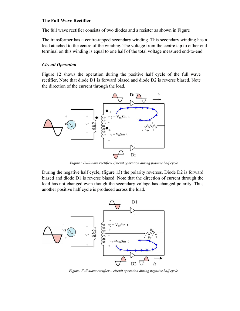
Full wave rectification can be achieved by two diodes. In a Full Wave Rectifier circuit two diodes are now used, one for each half of the cycle. Let V = Vm Sinθ the alternating voltage. Suppose diode resistance is 'R' and load resistance is R L. In case of forward biasing current flows through the diodes. But during reverse bias current.. The full wave rectifier circuit consists of two power diodes connected to a single load resistance (R L) with each diode taking it in turn to supply current to the load.When point A of the transformer is positive with respect to point C, diode D 1 conducts in the forward direction as indicated by the arrows.. When point B is positive (in the negative half of the cycle) with respect to point C.

With Neat Circuit Diagram And Waveforms Explain The Operation Of Full Wave Rectifier Circuit
FullWave Rectifier Rectifiers Basics Electronics

Full wave Rectifier with RL load and freewheeling diode YouTube

Full Wave Bridge Rectifier Circuit Diagram

Full Wave Rectifier Circuit Diagram and Working Principle » ElectroDuino
Fullwave Rectifier

Full Wave Rectifier simulation using PSPICE Simulate full wave bridge rectifier in PSPICE
InDepth Guide to Full Wave Rectifier Circuit Diagram, Waveform

How can make two diodes rectifier? rectifier diode Why two diodes are used in full wave
What is Half Wave and Full Wave Rectifier? Operation & Circuit diagram Circuit Globe

☑ Diode Rectifier Circuits

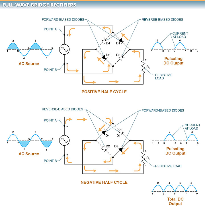
☑ Full Wave Bridge Rectifier Using Diode
Half Wave & Full Wave Rectifier Working Principle, Circuit Diagram, Output Voltage Electrical A2Z

voltage divider How to solve a a full wave rectifier with two diodes and a ground in the

Circuit Diagram Of Full Wave Bridge Rectifier With Capacitor

Full wave Rectifier Explained YouTube

What is a singlephase fullwave rectifier
Half Wave & Full Wave Rectifier Working Principle, Circuit Diagram, Output Voltage Electrical A2Z

CenterTapped FullWave Rectifier Operation … CircuitBread
The FullWave Rectifier The full wave rectifier consists of two diodes
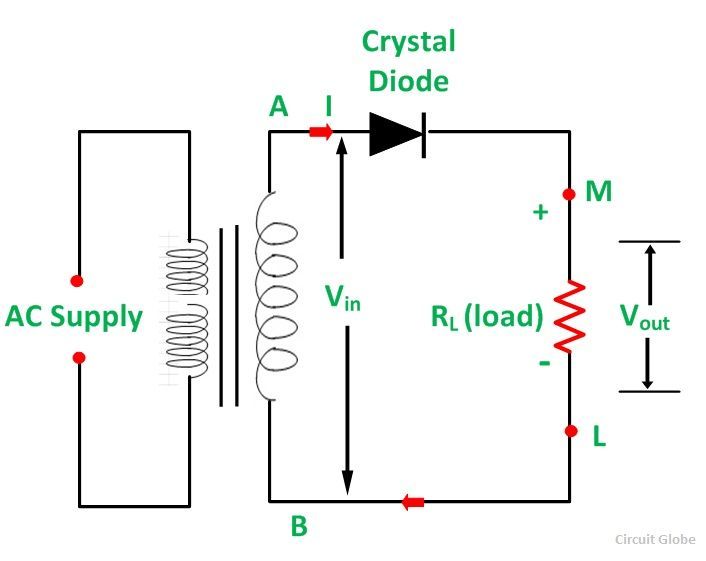
A rectifier circuit that uses a center-tapped transformer and 2 diodes to convert the complete Alternating current (AC) signal into a Direct current (DC). A complete Center-tapped Full Wave Rectifier circuit consists of four main parts, these are a Center-tapped transformer, two diodes, a resistive load, and also need an AC voltage source.. A full-wave rectifier is a circuit that allows a complete alternating current (AC) waveform to pass, turning an AC signal into a pulsed direct current (DC) signal. In contrast, half-wave rectifiers allow only one half (the positive half) of an AC waveform to pass. The negative part of the AC waveform is essentially wasted.